Cmos Inverter Circuit
Cmos inverter short circuit current 6 this component represents less than 20 of the dynamic switching.

Cmos inverter circuit. The power supply pins for cmos are called v dd and v ss or v cc and groundgnd depending on the manufacturer. V dd and v ss are carryovers from conventional mos circuits and stand for the drain and source supplies. These do not apply directly to cmos since both supplies are really source supplies. Cerda crystek corporation september 8 2010 page 1 clipped sinewave to cmos conversion circuit the above circuit converts a clipped sinewave waveform to a cmos waveform.
An inverter circuit outputs a voltage representing the opposite logic level to its input. Its main function is to invert the input signal applied. Szza043 4 use of the cmos unbuffered inverter in oscillator circuits c0 r c l figure 2. Electrical equivalent circuit of a crystal the quantities c and l are determined by the mechanical characteristics of the crystal.
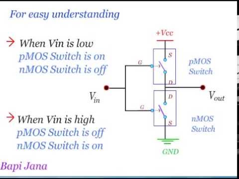
Pmos transistor cmos working principle. In cmos technology both n type and p type transistors are used to design logic functions. The same signal which turns on a transistor of one type is used to turn off a transistor of the other type. Up until this point our analysis of transistor logic circuits has been limited to the ttl design paradigm whereby bipolar transistors are used and the general strategy of floating inputs being equivalent to high connected to v cc inputsand correspondingly the allowance of open.
4 paulo francisco butzen and renato perez ribas fig.
Schematic Of A Cmos Inverter Circuit Download Scientific Diagram

7 2 Cmos Inverter

Cmos Based Inverter Circuit Operation Explained

Cmos Wikipedia

Draw A Circuit Diagram Of A Cmos Inverter Draw Its Transfer
What Is The Working Principle Of Cmos Inverter Quora

Cmos Wikipedia

Cmos Inverter Circuit Download Scientific Diagram

Cmos Inverter Digital Cmos Design Electronics Tutorial

Vlsi Design Mos Inverter

Cmos Inverter Circuit Allthingsvlsi

Cmos Inverter With Gate Of Pmos Transistor Always Grounded

Cmos Inverter

The Cmos Inverter Explained

Cmos Inverter Voltage Transfer Characteristics Vlsi Teacher

Mosfets And Cmos Inverter Elec2210 V1 0 Documentation

Cmos Inverter Theory Digital Vlsi Design Virtual Lab

Mosfets And Cmos Inverter Gadgets In 2019 Electronics Circuit

Cmos Inverters
Working Of Cmos Inverter Circuit

Basics Of Testing Cmos

Cmos Inverter Based Question From Sedra Smith Microelectronic

Spice Modeling Of A Cmos Inverter

Transistors Cmos Inverter Circuit Analysis Electrical

Cmos Inverter I Cmos Nor Gate I Cmos Nand Gate Eeeguide Com

Solved Consider The Cmos Inverter In Figure 16 21 Biased At Vd

Cmos Logic Circuits
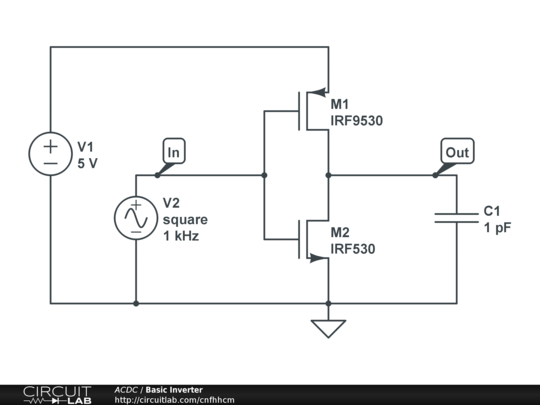
Basic Cmos Inverter Circuitlab

Cmos Logic Circuits

7 2 Cmos Inverter

Unit V Cmos Logic Cmos Logic Levels Mos Transistors Basic Cmos
Leakage Current In Sub Micrometer Cmos Gates

Schematic Diagram And Layout Of Cmos Inverter

Cmos Inverter I Cmos Nor Gate I Cmos Nand Gate Eeeguide Com

Cmos Inverter With Dual Threshold Transistor Stacking Dtts

Cmos Gate Circuitry Logic Gates Electronics Textbook

Cmos Wikipedia

Stick Diagram
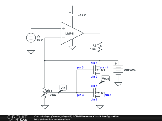
Cmos Inverter Circuit Configuration Circuitlab

Led Driving Transistor With The Output Of Cmos Inverter

Propagation Delay Of Cmos Inverter Vlsi System Design

Vlsi Design Mos Inverter

Inverter Using Transistor Wonderfully Cmos Inverter Circuit A726

Solved From The Figure Below Consider A Cmos Inverter Ci

Topic 8 Complementary Mos Cmos Logic Design Ppt Download

The Cmos Inverter

Optimal Cmos Inverter Design Using Differential Evolution Algorithm

Cmos Wikipedia

Figure 4 From Implant Dose Sensitivity Of 0 1µm Cmos Inverter Delay

Cmos Technology Working Principle And Its Applications
