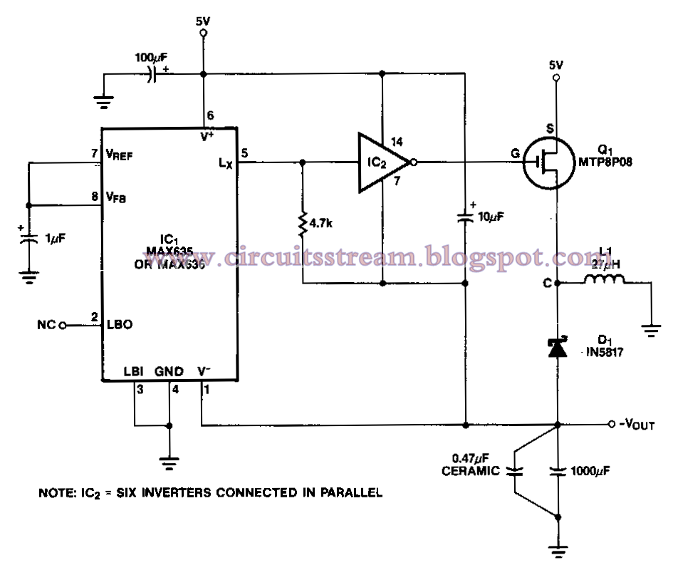
Electrical Inverter Circuit Diagram
Disconnect the jfet gates fron the circuit and measure the pull up voltage at pins 1114.
Electrical inverter circuit diagram. This is the circuit diagram of 3000w power inverter 12v to 230v modified sinus capable to deliver about 3000w 230v ac output from 12v input. This is the inverter circuit for professional only. A power inverter or inverter is an electronic device or circuitry that changes direct current dc to alternating current ac. The input voltage output voltage and frequency and overall power handling depend on the design of the specific device or circuitry.
When creating a circuit diagram its important to understand how common electrical engineering symbols are used and what they mean. Check out our guide to circuit symbols in lucidchart to get a head start. Principle behind this circuit. The basic idea behind every inverter circuit is to produce oscillations using the given dc and apply these oscillations across the primary of the transformer by amplifying the current.
A solar inverter helps in converting the direct current into alternate current with the help of solar power. Direct power is that power which runs in one direction inside the circuit and helps in supplying current when there is no electricity. Not being an expert on the use of the sg3524 i would do the following.


